Part structure
With the wide application of CNC machining technology, the complexity of the part structure is constantly improving. In some parts processing, positioning and clamping are very difficult, and it is not suitable for multiple positioning and clamping. The whole machining one-time forming technology is to rotate and turn the worktable according to the angle on the horizontal or vertical horizontal conversion machining center machine, and to process all the faces and holes of the parts in one time, and meet all the geometrical tolerance requirements of the pattern. The part of the boring and milling part is connected to the process handle to separate the process handle from the workpiece. As shown in Fig. 1, the part material is aluminum alloy 2A12-T4 profile, the outer circle φ 32mm, the K base surface and the hole φ 30mm, and the M base surface associated with the shape accuracy requirements are higher. If the clamping is positioned twice, the positioning error is large and the clamping is difficult. The use of non-unloading parts one-time forming technology, the position accuracy of the parts after processing is well guaranteed.
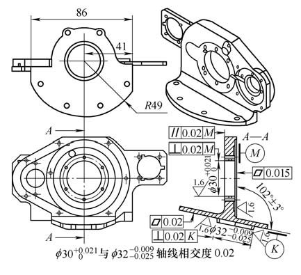
Figure 1 bracket diagram
2. Processing principle
Make full use of the multi-angle and all-round machining advantages of CNC machining center, and use the characteristics of small-speed deformation of high-speed and small-feed machining parts of cemented carbide milling cutters, and use the residual part of profile parts as the positioning and pressing process handle, using UG software automatically. The programming function ensures the consistency of the whole machined parts and the matching of the faces.
3. Process plan
(1) As shown in Figure 2, the part has a single side of 0.5mm, roughing each surface and hole, and the residual part of the profile is reserved as a process mounting handle. The screw hole 3×φ 6.5mm is drilled at the process handle. Hole 3 × φ 11 mm, depth 6 mm, drill hole 2 × φ 4 mm (positioning pin hole). After the parts are stabilized (to eliminate internal stress), the E-reference large face is ground to ensure a flatness of 0.008 mm.
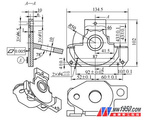
Figure 2 Semi-finished stent sketch
(2) As shown in Figure 3, design and manufacture special curved plates, using 40C r material of quenched and tempered steel, grinding to ensure the flatness of the mounting surface is 0.006mm, drilling tapping 3×M6-6H thread, point drilling reaming 2 ×φ 3mm (Positioning pin hole), drilling 2×φ 13mm curved plate to fix the through hole, milling and letting the flat hole (for finishing the part K surface of Fig. 1 and φ 32mm hole, the rod milling cutter can be probed into the flat hole) .
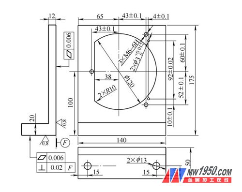
Figure 3 dedicated curved plate fixture diagram
(3) As shown in Fig. 4, the principle of one pin and two pin positioning is adopted, and the special curved plate of Fig. 3 is installed in the working position of the horizontal machining center near the center position, and the frame surface is verified to be perpendicular to the work surface, and the bolt is fastened and bent. Figure 2 grinding E plane, 2 × φ 4mm hole positioning, according to Figure 1 finishing parts of the surface, finishing milling outer circle φ 32mm and K base surface, finishing M base surface and back surface, fine boring hole φ 30mm, etc., to ensure Size and shape accuracy.
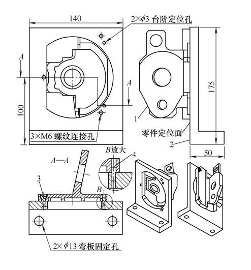
Figure 4 Schematic diagram of part finishing
1. Pre-finishing parts 2. Special curved plate fixture
3. Hexagon socket head cap screws (M6×12mm, 3 pieces) 4. Step positioning pin (2 pieces)
(4) Before the machining of the part is completed, the NC program executes the pause command (M00), and a hard sponge pad (approx. 20 mm × 300 mm × 300 mm) is placed in the lower part of the part to be dropped. According to Fig. 1, the φ 6mm cemented carbide milling cutter is used to penetrate into the flat hole of the special bending plate fixture, and the depth of each layer is 0.1mm, and the outer contour of the part is welded by R49mm, 86mm and the residual process handle to make the workpiece and process. The handle is detached, the part is dropped on the pre-placed hard sponge pad (to avoid the deformation of the part), and the residual flash around the part R49mm is cleaned by the fitter.
4. Implementation effect
Independent innovation on the support parts using the overall machining one-time forming technology, the mass production of the bracket parts shown in Figure 1, through the three-coordinate detection, the shape and position accuracy statistics are as follows: K base plane flatness ≤ 0.012mm, M base plane flatness ≤0.01mm, the parallelism of the back surface of M is ≤0.015mm, the perpendicularity of φ 30mm to the base surface of M is ≤0.013mm, the perpendicularity of φ32mm to the base of K is ≤0. 015mm, the intersection degree of φ 30mm and φ 32mm axis is ≤0.014mm. The dimensional accuracy of the parts in the mass production is stable, and the production efficiency is greatly improved.
5. Application and scope of expansion
The overall machining process of the part can be used not only in the horizontal machining center, but also in the vertical and vertical conversion machining centers. As shown in Fig. 5, the parts can be integrally formed by a rectangular parallelepiped aluminum alloy profile on the five-axis machining center, and the process handle is layered and milled; as shown in Fig. 6, the parts can be cut with a rectangular parallelepiped aluminum alloy profile on the three-axis machining center. Pressing plate processing, the left and right supports are integrally formed at the same time, and the layered milling is performed to the residual process table.
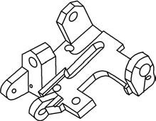
Figure 5 conversion base diagram
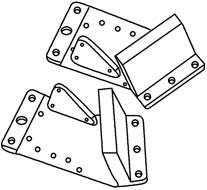
Figure 6 left and right bearing diagram
6. Conclusion
One-piece machining process of parts is mainly used for machining parts with difficult positioning and clamping. It can be combined with machining process to improve work efficiency and ensure the accuracy of shape and position. It can be used for symmetrical assembly parts in pairs, reducing the number of clamping times. It saves the cost of tooling production; it is suitable for high-speed small-feed layer-by-layer scanning processing. When cutting, the cutting force is small, the cutting heat is small, and the parts are not easy to produce stress deformation. This processing concept is gradually being promoted by our company.